If you work in data centers, 5G telecom networks, or high-capacity enterprise switching, you’ve probably stared at a rack of optical transceivers before—small, square, gold-plated modules that are the unsung heroes of modern digital connectivity. But if you’ve ever wondered why some transceivers run for years without a hitch and others overheat mid-deployment, you’re not alone. As a supplier of optical transceivers that’s worked with hundreds of data center and network operators, I can tell you that cooling isn’t an afterthought for high-density installations—it’s make-or-break for performance, reliability, and long-term costs. Let’s break down exactly what those cooling requirements look like when you’re packing transceivers as tight as possible in a rack. Optical Transceivers
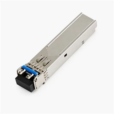
First, let’s ground this in how optical transceivers generate heat in the first place. Every transceiver converts electrical signals from network equipment into optical signals for fiber, and vice versa. That conversion relies on two key components that produce heat: the laser diode (for transmit functions) and the photodiode (for receive functions), plus small supporting electronics like transimpedance amplifiers (TIAs) and clock and data recovery (CDR) chips. For high-speed transceivers—think 400G, 800G, and the upcoming 1.6T units—these components run far hotter than older 10G or 100G modules. A 400G DR4 transceiver, for example, generates roughly 5 to 7 watts of power, while an 800G OSFP unit can easily hit 10 to 12 watts per module. Multiply that by 16 transceivers per line card, 8 line cards per rack, and you’re looking at over 1,200 watts of heat just from transceivers in a single rack—that’s equivalent to running a large microwave nonstop, all tucked into a 19-inch rack where there’s barely room for air to circulate.
The biggest mistake we see operators make with high-density installations is assuming that generic rack cooling will work for transceivers. Traditional rack cooling relies on front-to-back hot-aisle/cold-aisle airflow, where cold air from a data center’s HVAC blows into the front of the rack, passes over equipment, and pulls heat out the back. But when transceivers are packed into the front of a line card (a common practice to maximize port density), that airflow has to pass through a tight, clustered group of modules. Many cheap generic transceivers don’t account for this, so their internal temperature sensors start hitting thermal throttling limits as soon as adjacent modules block airflow. Thermal throttling is the transceiver’s built-in safety feature: it slows down data transmission to reduce heat, which is a death sentence for high-speed networks that demand consistent latency and throughput. We’ve had clients come to us mid-deployment saying their new 800G transceivers were only hitting 50% of their rated speed, only to realize the rack’s airflow was too low to keep the clustered modules cool.
So what are the non-negotiable cooling requirements we design every transceiver to meet, based on real-world deployment data? Let’s start with ambient temperature thresholds. Most standard transceivers are rated for a commercial ambient range of 0°C to 70°C, but high-density installations change that. When transceivers are operating in a packed rack, the air temperature around each module isn’t the data center’s 22°C setpoint—it can be 5°C to 10°C hotter at the back of the rack, and even higher in dense deployments. That means our transceivers are tested to handle a maximum operating junction temperature of 85°C, not the 70°C ambient rating. We also add an extra 15°C of headroom: if the ambient air around a transceiver hits 55°C, the module shouldn’t throttle until its internal temperature is 80°C, giving operators a buffer before performance drops. That buffer is critical for high-density racks where airflow is often not perfectly uniform.
Next, airflow is non-negotiable, and it’s not just about volume—it’s about direction and uniformity. Optical transceivers rely on front-to-front or front-to-back airflow (we design modules for both, since some operators use rear-to-air designs) to pull cool air over their heat-generating components. Our transceivers have built-in heatsinks that are calibrated to maximize heat dissipation with just 0.5 meters per second (m/s) of airflow, which is the minimum for high-density deployments. But if airflow drops below 0.4 m/s, even a well-designed transceiver will hit thermal limits in under an hour. We test all our modules at airflow levels as low as 0.3 m/s, so we can tell operators exactly what they need: if your racks are 40U and you’re installing 32 transceivers per line card, you’ll need rack fans that deliver at least 0.5 m/s of uniform airflow across the entire card, not just at the top of the rack. A common shortcut operators take is using fewer, stronger fans, but that creates hot spots at the middle and bottom of the line card, where transceivers end up overheating first.
Another often-overlooked requirement is power density correlation. Transceiver power output directly ties to heat, and high-density installations have a power density that’s 2 to 3 times higher than older 100G deployments. For example, a 400G transceiver that generates 5W is manageable in a low-density rack, but 800G transceivers at 12W each mean 192W per line card, which adds up to 1,536W per rack when using 8 line cards. Our engineering team works closely with clients to size cooling systems specifically for their transceiver load, not just their rack’s total equipment power. If an operator is upgrading from 100G to 800G transceivers, we don’t just sell the modules—we advise them to adjust their HVAC setpoints or add rack-level auxiliary fans to handle the extra heat. We once had a client in a colocation data center that tried to skip this step, and they ended up replacing 200 overheated transceivers in three months, a cost that was 10x more than the cooling upgrades we recommended upfront.
Then there’s the matter of long-term reliability. Transceiver heat isn’t just a performance issue—it’s a longevity issue. Every 10°C increase in operating temperature cuts a semiconductor component’s lifespan by roughly 50%, per semiconductor reliability standards. That means a transceiver running at 80°C will last half as long as one running at 70°C, and a transceiver running at 90°C will last just a quarter of its expected life. For high-density installations where replacing transceivers is a labor-intensive task (you have to pull line cards, swap modules, and test the network), this adds up to massive operational costs. We design our transceivers to keep their junction temperature below 75°C even in the hottest, low-airflow parts of a dense rack, which extends their lifespan to over 10 years—double the lifespan of uncooled, generic transceivers. That’s a huge selling point for operators who want to reduce maintenance and replacement costs over time.
We also have to talk about edge cases, because high-density installations aren’t just in large data centers. 5G small cell sites, for example, are high-density too, but they have way less cooling capacity than a data center. A small cell may have a single line card with 8 transceivers, and it relies on passive cooling (no fans) to keep them running. For these deployments, we design low-power transceivers that generate just 3W each, with heatsinks optimized for passive dissipation. That means the transceiver can run without a fan even when ambient temperatures hit 45°C, which is common in outdoor small cell sites in warm climates. We’ve lost count of how many small cell operators have told us that generic transceivers overheat and fail in their sites, but our units have run for years without issue because we tailored their cooling for edge, high-density environments.
A common question we get is: “Can I use a higher-power transceiver with existing cooling?” The short answer is no, not without re-evaluating your setup. If you’re upgrading from 400G transceivers (5W each) to 800G transceivers (12W each), you can’t just swap the modules and expect the same cooling to work. You’ll need to increase airflow by at least 25%, or add additional cooling capacity to the rack. We recently worked with a financial services client that was moving to 800G for their core data center, and their existing cooling was only rated for 500W per rack. We recommended a mix of 800G transceivers with optimized heatsinks and auxiliary rack fans that increased airflow by 30%, which let them run 80 transceivers per rack without overheating. That’s the kind of tailored approach that works, instead of a one-size-fits-all solution.
Another key point is compatibility with form factors. High-density transceivers use compact form factors like QSFP-DD, OSFP, and SFP-DD, which are smaller than older modules and often have less space for internal heatsinks. That’s why we invest in advanced heatsink design—we use finned heatsinks made of high-conductivity copper that fits within the form factor’s limits, but still dissipates heat 20% better than standard aluminum heatsinks. We also add thermal interfaces that fill gaps between the transceiver’s internal components and the heatsink, reducing thermal resistance and making sure heat doesn’t get trapped inside the module. For operators, that means even a compact, high-density transceiver doesn’t have to sacrifice performance to stay cool.
We’ve seen a lot of myths around transceiver cooling, too. One big myth is that all transceivers need active cooling, but that’s not true for all high-density installations. Passive cooling works for up to 8 transceivers per line card if the airflow is good, but once you get past 16, you need at least a small heatsink or auxiliary fan. Another myth is that higher airflow always means better cooling—too much airflow can cause vibration, which can damage delicate transceiver components or loosen fiber connections. We design our transceivers to work with airflow levels between 0.4 and 1.5 m/s, which is the sweet spot for most high-density racks, avoiding both hot spots and vibration issues.
At the end of the day, the cooling requirements for optical transceivers in high-density installations boil down to three core things: match the cooling to your transceiver’s power output, ensure uniform airflow across the entire line card, and build in headroom for real-world operating conditions. As someone who’s been in the optical transceiver industry for over a decade, I can tell you that cutting corners on cooling is the fastest way to run into performance issues, unexpected replacements, and higher operational costs. Our team doesn’t just sell transceivers—we work with clients to assess their rack layouts, airflow, and cooling infrastructure to make sure our modules fit seamlessly into their high-density deployments, with no overheating, no throttling, and no unexpected downtime.
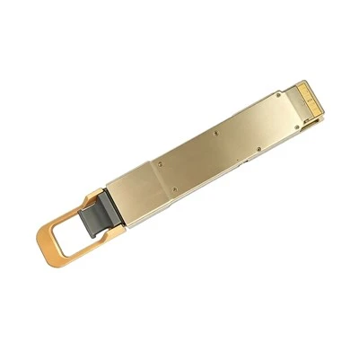
If you’re planning a high-density deployment, upgrading your network to 800G or 1.6T transceivers, or dealing with recurring overheating issues in your racks, our team can help you assess your current setup, recommend the right transceivers, and work with you to optimize your cooling strategy. Don’t let poor cooling derail your network’s performance or add unnecessary costs—reach out to our team to start a conversation about your specific needs.
Infrared LED Emitters References
- Optical Transceiver Thermal Design Guidelines, IEEE 802.3 Working Group, 2022.
- Data Center Thermal Management Best Practices, Uptime Institute, 2021.
- Semiconductor Reliability and Temperature Correlations, JEDEC Solid State Technology Association, 2020.
- High-Density Optical Transceiver Form Factor Standards, Multi-Source Agreement (MSA) Alliance, 2023.
Zhejiang Chengmei Technology Co., Ltd.
As one of the most professional optical transceivers manufacturers and suppliers in China, we’re featured by quality products and good price. Please rest assured to wholesale bulk premium optical transceivers made in China here from our factory. Also, quotation is available.
Address: No. 383, Jinhe Road, Qinshan Street Industrial Park, Haiyan County, Jiaxing City, Zhejiang Province
E-mail: shiwei@cm-semi.com
WebSite: https://www.cmfiber.com/
